And one of the videos that caught our eye was mmidgal's Arduino Air Drums.
He had constructed a 3 piece drum kit with 4 sounds using a MIDI interface, 3 accelerometers, a Photocell, some USB ports, two garden rakes and a couple of slippers. All in an afternoon, according to Gizmodo. [which we SERIOUSLY doubt because it took us a little over a week]
Shyam came up with the idea a couple of weeks before our semester end exams, and I was a little skeptical at first, but then I remembered my dream of always wanting to play kickass drums. Because, lets face it, drums are cool. Maybe not as cool as guitars, but still, pretty cool.
So, on day 1, Shyam and I make our way to Malleshwaram, to meet at Akshay's house. We decided everything that we needed to get, and set our budget at around 4k and left to
SP Road.
So, here comes the slightly technical bits:
Stuff we bought were:
1. The Arduino Uno
2. ADXL335 accelerometers [x3]
3. USB cables [x4]
4. USB females [x8]
5. 5 pin DIN connector
6. A no-company-comes-without-a-box MIDI to USB converter for Rs. 8oo, because the M-Audio Uno that the mmidgal recommends is 2.7k. lol.
7. A bunch of Photocells (they cost about Rs. 5 a piece, so we thought we'd build a keyboard later with them)
All these items we bought, solely on the recommendation of the video and we didn't realize that some of them might be not necessary. Like the DIN connector and the MIDI to USB converter cable. :|
Okay, before we continue, a little introduction into MIDI:
MIDI (Musical Instrument Digital Interface) uses a form of serial to communicate at a data rate of 31250 bps with each byte made of 8 bits plus a stop and start bit. MIDI commands are most often three bytes in length but sometimes more or less. The Serial-MIDI converter currently only handles three byte MIDI commands.The first byte is called the Status byte and contains both the type of MIDI command and the channel number. The high nibble of this byte tells the MIDI device what it is doing, such as Note Off, Note ON, Control change etc... The low nibble is the channel, it is used to differentiate between devices that are on the same MIDI bus and varies from 0 to 15.The second byte is the Pitch byte and is simply the note being played, stopped, altered etc... This byte is in the range of zero to 127.The third byte (when used with Note-On or Note-Off) is the velocity, which is a form of volume for the note being played. Imagine that you hit a drum softly, then the velocity would be a low number, but if you really whaled on it then the velocity would be higher. This byte is also in the range of zero to 127.
And a little bit about the ADXL335 accelerometers:
Breakout board for the 3 axis ADXL335 from Analog Devices. This is the latest in a long, proven line of analog sensors - the holy grail of accelerometers. The ADXL335 is a triple axis accelerometer with extremely low noise and power consumption - only 320uA! The sensor has a full sensing range of +/-3g.There is no on-board regulation, provided power should be between 1.8 and 3.6VDC.Board comes fully assembled and tested with external components installed. The included 0.1uF capacitors set the bandwidth of each axis to 50Hz.
So all that it is is a little chip with an IC and a few capacitors on it. There are 6 terminals;
VCC
GND
X OUT
Y OUT
Z OUT
Self Test (ST)
Which are pretty self explanatory, basically the value of the at the three output pins change when motion in their respective axis is carried out. And about the Self Test pin, the data sheet had this to say:
The ST pin controls the self-test feature. When this pin is set to VS, an electrostatic force is exerted on the accelerometer beam. The resulting movement of the beam allows the user to test if the accelerometer is functional.The typical change in output is −1.08 g (corresponding to −325 mV) in the X-axis, +1.08 g (or +325 mV) on the Y-axis, and +1.83 g (or +550 mV) on the Z-axis. This ST pin can be left open-circuit or connected to common (COM) in normal use.
er.. WE CAN LEAVE IT OPEN!
The acclerometer that we used were built by NSK Electronics, and the board said that that the supply voltage should be 5V. We rarely experienced any overheating problems and pretty faithful responses to movement. One gripe that we did have was when we moved the accelerometer in the Z direction, there was a change in signal coming from the YOUT pin which made it hard for us to program the ride sound.
Okay that's all cool, but how the hell are we going to connect them to the Arduino?!?
The cool thing about the Arduino Uno is that it has a set of analog and digital pins that can be used for either outputs or reading inputs! A very simple example is illustrated in the Arduino website: Analog Input Digital Output.
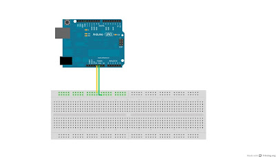
All we had to do was hook up the 5V pin and GND pin on the Arduino to two lines on our breadboard and use those to feed our Accelerometers.
The readings from our Accelerometers have to be fed into the analog inputs on the Arduino to be read, so, we chose the Z axis as the one we're going to use for everything and hooked those up to the bread board and the Arduino.
So now we have our inputs for the snare sound, the bass drum sound and the hi-hat sound.
Lets add a photocell in a voltage divider configuration with a 47k resistor to help us decide whether the hi-hat accelerometer is going to play closed hi-hat or open hi-hat.
Here is a neat instructable explaining how the voltage divider works.
So that's, basically our circuit. We made use of USB cables and connectors to help manage all the wires, otherwise it would have been a HUGE mess!
 |
| Be sure to remember the colours! |
 |
| And be sure to label them too! |
 |
| Secured the accelerometer to the drum sticks using lots and lots of sticky tape. Lots. |
 |
| And buy plenty of different coloured wires, trust me, they are super useful. |
Once you're done with the sticks, your circuit will look more or less like this:
 |
| The sticks we used were Tama Rhythmic Fire size 7A sticks. -_- |
All that's left are the 'pedals' and programming, which I will be covering in the next blog post and we will hopefully be done with the demonstration video!!
-Bhargav


hallo friends
ReplyDeletei am a very imprese to see air drum project. good, as i am arduino lover. and music lover. if you don't mind please, send mail address.
my e-mail: gthakar4@gmail.com
hope might help me.
gaurang
Hey Guys,
ReplyDeleteGreat project! Where on SP road did you guys buy the parts?
Hey Barney! Sorry for the epicly late reply!
ReplyDeleteWe bought most our Arduino and Accelerometers from NSK, The USB cables and other things, we bought them in some small shops, they seemed to be available everywhere. :P
I have a question... where I hook up the black cable? and what happened with the light sensor? ._. How do I connect the light sensor? I need your help please, I loved this project and would like to make assembling the "Air Drums".
ReplyDeleteHey Angelica!
DeleteWhich black cable are you talking about? :P
The photo sensitive resistor wasn't responsive enough to 'open' and 'close' the hi-hat part of the drum kit.
The way the photo-sensitive resistor is connected is explained in this instructable - http://www.instructables.com/id/Arduino-Expermentation-Kit-How-to-get-Started-wi/step11/Light-Photo-Resistors-CIRC09/
If you have any more questions, feel free to ask!
Hope this helps!
Thanks for the reply!
ReplyDeleteI understand the connection of the light sensor.
About the black cable, we have the "pin" of USB, wired blue, black, green and yellow, but what does the black wire?.
And if you had more pictures about this project ... Am I the could send to my email?.(angelicatapia7@gmail.com)
Sorry if I do lots of pointless questions, but I'm new in this world of "Arduino".
Thanks for everything :)
Hey Angelica!
DeleteThanks for noticing the mysterious black wire :P
If you notice in Part 2 of this blog post, under the "A few things that we wanted to add were:" part, we mentioned "A ride sound when the stick is swung in the X direction. This we could never get right because it was happening even when the stick was swung in the Z direction."
The black wire was basically connected to the X-axis of the accelerometer, but I don't think we used in the final design.
As for pictures, I'm not sure I still have them as this is a pretty old project. But anyway, I'll dig around for a bit and see if I can find some :)
Keep the questions coming!
Thanks!
Hello!
ReplyDeleteI'm a Korean and college student Jiwon.
I've seen the air drum movie you made.
And i think i want to make it.
I understanding of the hardware.
But i do not know something.
How do the connect a laptop with hardware? and Did you use any software?
How do the make a sound?
I need your help. Maybe, There, There are many mistakes. I'll apologize in advance.
I'll wait for your reply.
Jiwon
This comment has been removed by the author.
ReplyDeleteGsm Modem http://gsmmodem.in
ReplyDeleteGsm Module http://evergreenelectronics.in
where is second part?
ReplyDeleteHello how are you
ReplyDeleteI would like to learn how to add sound to each function?
Please help me!
I am new to the area and really enjoyed your project.
liking resposde that can help me!
klaisson@yahoo.com.br
ReplyDeleteok
Dude please tell me "How is that sound coming out" ?
ReplyDeleteI want to know code of arduino air drums . Please help me !
ReplyDelete